Let's build an amp! Greg's journey to electrocution

DIY Studio Stuff
Post Reply
User avatar
liv_rong
Posts: 1953
Joined: Thu Jan 19, 2017 7:32 pm

Re: Let's build an amp! Greg's journey to electrocution

Post by liv_rong »

Greg_L wrote: Mon Jun 18, 2018 8:35 pm This afternoon's project. First full recording with the homebuilt Deluxe Retard.

The Witch.mp3
Sounds good man!

Been waiting to listen to this since you posted it. Nice!
User avatar
Greg_L
Posts: 20668
Joined: Wed Jan 04, 2017 1:07 pm
Location: Where the knuckle meets the poophole

Re: Let's build an amp! Greg's journey to electrocution

Post by Greg_L »

liv_rong wrote: Fri Jun 22, 2018 8:09 pm

Sounds good man!

Been waiting to listen to this since you posted it. Nice!
Thanks man. :coolstorybro:
Rebel Yell
User avatar
Greg_L
Posts: 20668
Joined: Wed Jan 04, 2017 1:07 pm
Location: Where the knuckle meets the poophole

Re: Let's build an amp! Greg's journey to electrocution

Post by Greg_L »

Okay you ballbags. If you're sick of this thing, don't worry, we are reaching the end of the journey.

Today I switched the entire amp to HIGH VOLTAGE!!!!!

My power transformer has two sets of secondary windings. I can only characterize them as "soft" and "hard". Lol.
Here's the PT schematic:
w025130sch - Copy.JPG
I labeled the secondary windings in colored boxes. We'll focus on the red box. Look at the red/wht wires. Together they provide 540 VAC to the rectifier plates. This AC voltage is then rectified to DC and sent out to the amp. With my 122v wall voltage, I was actually getting 553 VAC at the rectifier. Seems like a lot, but it isn't. The DC output after rectification was only 380 VDC. That's what the entire amp has to draw from. How does this affect the amp? It doesn't, really. Everything runs at a proportionately lower voltage than what Fender specified back in 1963. How does it affect the sound? It does somewhat. The breakup is softer and sooner and there is reduced clean headroom - not unlike using a Variac to cut power to an amp. But mainly my amp works great and that obviously was the plan all along. So with it passing the lower power test, time to go big.

Original Fenders used PTs that pumped out about 660 VAC, which is right in range with the other wires on my PT. Look at the red wires in the red box. They kick out 680 VAC! And mine, unloaded, checked and verified, actually puts out 700 VAC. Earlier we talked about getting hit with high voltage in a live amp, try 700 volts on for size. Anyway, I unhooked my other wires and hooked into the red high voltage wires. I also, again, beefed up the first node filter caps. They're 500v handling now. Plenty safe. I haven't jotted down my readings yet, but I've gained abut 100 volts on the B+ power rail and everything falls pretty much right in spec with the original Fender design. My plate voltages, filter cap node voltages, etc are all pretty much spot on. And nothing exploded. So we're good to go. Full power. It does sound a lot cleaner and punchier. Better clarity and headroom for sure. The tremolo works better. So I'd say it's a win. I like it a lot. :coolstorybro: :coolstorybro: :coolstorybro:

I'll try to make a little video of the amp on my new scope so you can see wtf that shit looks like.
You do not have the required permissions to view the files attached to this post.
Rebel Yell
User avatar
rayc
Posts: 8488
Joined: Wed Jan 04, 2017 6:31 pm
Location: South of Bundaberg North of Brisbane

Re: Let's build an amp! Greg's journey to electrocution

Post by rayc »

AND sounds like I hope. Excellent journey.
Cheers
rayc
User avatar
Greg_L
Posts: 20668
Joined: Wed Jan 04, 2017 1:07 pm
Location: Where the knuckle meets the poophole

Re: Let's build an amp! Greg's journey to electrocution

Post by Greg_L »

rayc wrote: Mon Jun 25, 2018 7:50 pm AND sounds like I hope. Excellent journey.
It sounds awesome!
Rebel Yell
User avatar
Greg_L
Posts: 20668
Joined: Wed Jan 04, 2017 1:07 pm
Location: Where the knuckle meets the poophole

Re: Let's build an amp! Greg's journey to electrocution

Post by Greg_L »

Still tinkering.

I fixed my input jacks. Having them backwards was just eating at my head incessantly, so I put them right. Now 1 is the high input, as it's supposed to be, and 2 is the lower input. And lo and behold, the impedance got better. Not that a few ohms matters, but it's exactly right now.

And I made this little dummy load...
Image

Now I can scope my amps without hearing that goddamn 1k sine wave.
Rebel Yell
User avatar
rayc
Posts: 8488
Joined: Wed Jan 04, 2017 6:31 pm
Location: South of Bundaberg North of Brisbane

Re: Let's build an amp! Greg's journey to electrocution

Post by rayc »

That's an interesting idea.
Cheers
rayc
User avatar
Greg_L
Posts: 20668
Joined: Wed Jan 04, 2017 1:07 pm
Location: Where the knuckle meets the poophole

Re: Let's build an amp! Greg's journey to electrocution

Post by Greg_L »

rayc wrote: Sun Jul 01, 2018 7:45 pm That's an interesting idea.
It's just gotta take the place of a speaker for testing. Even with the attenuator set as a dummy load, that damn sine wave sound leaking out of it is maddening.

I doubled it up and here it is attached. Two 100w 8 ohm resistors in series for a 16 ohm speaker simulation dummy load.
Image


Also, you can see the "8" and "7" written above the auxiliary power plug. That thing now functions as bias test points. I can check my bias by probing inside that thing and adjust externally.
Rebel Yell
User avatar
rayc
Posts: 8488
Joined: Wed Jan 04, 2017 6:31 pm
Location: South of Bundaberg North of Brisbane

Re: Let's build an amp! Greg's journey to electrocution

Post by rayc »

Greg,
You think around corners. Problem solvers are the future but problem foresight, like yours, paves the way.
Cheers
rayc
User avatar
Greg_L
Posts: 20668
Joined: Wed Jan 04, 2017 1:07 pm
Location: Where the knuckle meets the poophole

Re: Let's build an amp! Greg's journey to electrocution

Post by Greg_L »

rayc wrote: Sun Jul 01, 2018 9:06 pm Greg,
You think around corners. Problem solvers are the future but problem foresight, like yours, paves the way.
Well thanks Ray, but I can't take credit for this. Little dummy loads have been around quite a while. I got the idea from watching techs on youtube. :lollers2:

I found that little pair on amazon for 5 bucks delivered in two days. Hot damn. Amazon may be killing traditional retail, but it's not like I can just go anywhere and find stuff like that.

The 100w rating might be a little dicey behind a Marshall, but it's plenty sturdy enough behind this Fender build.

Speaking of....I also did a rough wattage estimate using my new scope...and this thing pumps out about 22 watts RMS, which is right where it should be. I'll show all that if/when I ever make a video. :facepalm:
Rebel Yell
User avatar
Lt. Bob
Posts: 6577
Joined: Wed Jan 04, 2017 3:02 pm

Re: Let's build an amp! Greg's journey to electrocution

Post by Lt. Bob »

awesome mang!

I think it's time for us to chat .... PM me a number and good times to call and I'll give ya' a ring next week.
User avatar
Greg_L
Posts: 20668
Joined: Wed Jan 04, 2017 1:07 pm
Location: Where the knuckle meets the poophole

Re: Let's build an amp! Greg's journey to electrocution

Post by Greg_L »

Lt. Bob wrote: Mon Jul 02, 2018 1:39 am awesome mang!

I think it's time for us to chat .... PM me a number and good times to call and I'll give ya' a ring next week.
PM sent.


So in other news, I'm still fine tuning this thing. I've found a little oscillation happening in the reverb circuit. Not quite sure what to do about that yet but I'm working on it. The oscilloscope is paying off even with my lack of skill in using it. I think that might be contributing to that faint little brittle sound I sometimes get. The higher voltage setup is great though.
Rebel Yell
User avatar
WhiskeyJack
Site Admin
Posts: 11413
Joined: Sun Jan 12, 2014 11:48 pm
Location: Canada
Contact:

Re: Let's build an amp! Greg's journey to electrocution

Post by WhiskeyJack »

Greg_L wrote: Tue Jul 03, 2018 2:19 pm I think that might be contributing to that faint little brittle sound I sometimes get.
Is that the thing i was hearing way back in the prelim sounds you posted? or did you beat that already?
:happytrees:
User avatar
Greg_L
Posts: 20668
Joined: Wed Jan 04, 2017 1:07 pm
Location: Where the knuckle meets the poophole

Re: Let's build an amp! Greg's journey to electrocution

Post by Greg_L »

WhiskeyJack wrote: Tue Jul 03, 2018 2:54 pm

Is that the thing i was hearing way back in the prelim sounds you posted? or did you beat that already?
Yup, same thing, although it's better. It's still there, just barely. I'm thinking the amp has to break in more, and I know I have some oscillation happening.

I recorded a Super Reverb the other day and it had the same type of sound, but mine is a little more "crispy". So I think it's partly that sound just being there because that's how it is, partly maybe the newness of my amp, and partly electrical weirdness happening inside my amp right now.

I actually am not stressing it too much because it doesn't show up on tracks in a mix, and you can't hear it in the room. It's subtle but the mic finds it. But I am gonna track it down and do whatever I can to minimize it just for my own mental health. And I'm definitely going to fix that oscillation. That stuff is an amp killer.
Rebel Yell
User avatar
Greg_L
Posts: 20668
Joined: Wed Jan 04, 2017 1:07 pm
Location: Where the knuckle meets the poophole

Re: Let's build an amp! Greg's journey to electrocution

Post by Greg_L »

Yall wanna nerd out for a second?

Caution - lots of info ahead. All of this is just my understanding and how I think of it. I might be wrong on some of this, but this is how I "get it".

Here's a pic of my scope screen showing oscillation.
Image

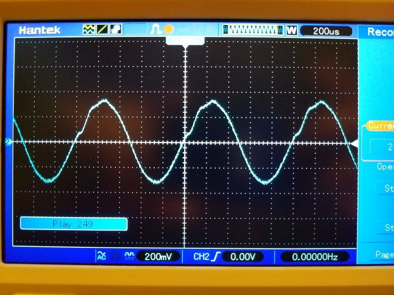
This is the 2nd gain stage of the vibrato channel. V2b - second tube, second stage. FYI, 12AX7s are actually two tubes in one. Anyway, signal goes into the input jack straight to the first stage - V2a, it comes back to the volume pot, and the volume pot controls the level that gets sent on to this stage. This should be a nice even smooth sine wave. But it aint. Those little hiccups in there are oscillation. The tube is running a little bit haywire. Why? I'll show you.

This is the next tube socket - V3.
Image

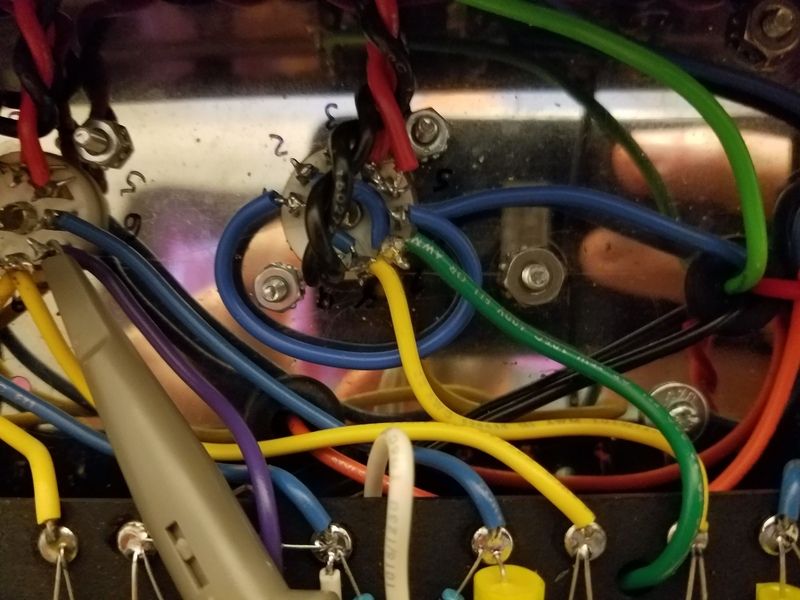
This tube takes a split of the signal from V2 and sends it through the reverb tank. The other half of the split V2 signal goes to the next gain stage - V4b. But we're only worried about this V3 half for now. Both halves of this tube are used to push the signal through the massive load that is the reverb transformer and tank. The reverb tank is essentially like a speaker load. With the reverb tank disconnected, or with this V3 tube removed, my sine wave at the previous stage was nice and even. So the problem lies with this tube/wiring - generally reverb related. See that little loop of blue wire connecting two tube pins? That wire bridges the plates of the tube and carries very high voltage. This wire was inducing spasms into the virtually empty wires around it. The green wire is a grid wire that carries actual guitar signal so there's very little voltage in there. And the yellow wire is a cathode wire - basically empty. It sets the operating bias of the tube. So those two weak ass wires are easily influenced by something as brutal as high voltage plate wires. When I'd move the blue looped wire around with a chopstick, the signal went batshit crazy and into full-on oscillation. The tube was losing it's mind. So I just desoldered that wire and flipped it around to loop to the other side of the tube socket. I should have done that to begin with, but whatever. My kinky signal at the V2b grid went nice and clean and perfect. Yay!

So here's where it is now.

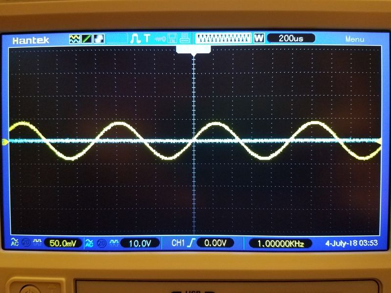
These pics show the scope set for two channels. First off....

The yellow line is my signal input at the input jack. It looks big, but that channel of the scope is scaled down to show fine details. For the yellow signal, each Y-axis square on the screen is 50 mv. So as you can see, it's about 50 mv each way, or 100 mv peak to peak. Easy, right? That's like a very weakish guitar signal. But it's steady and set to 1khz.

The blue line is the output channel probing the speaker jack. It's going to get a much more substantial signal, so it's scaled to 10v per division. That's 200 times the scale but that's so you can see them on the same screen and on top of each other. If we set the blue channel to the yellow channels scale, the output signal would fly off the screen through the ceiling.

But that's just the set up. The yellow signal will be unchanged because it's steady at the input jack. Nothing we do on the amp affects that testing point. The blue line is what we're watching.

So here are the signals with the volume on 0. The yellow line is our input signal, the blue line is flatlined because the volume is on 0, duh. There's no output to measure.
Image


And here we are with the volume on 5. The yellow signal is still the same because it's being read at the input jack and that doesn't change, but now look at the blue line. That's being read at the speaker jack. We have signal. And a good amount of it. But it's still pretty clean. The waves look about the same size, but remember the scaling. We're only at 50mv peak going in, but we're tipping over 10 whole volts coming out.
Image


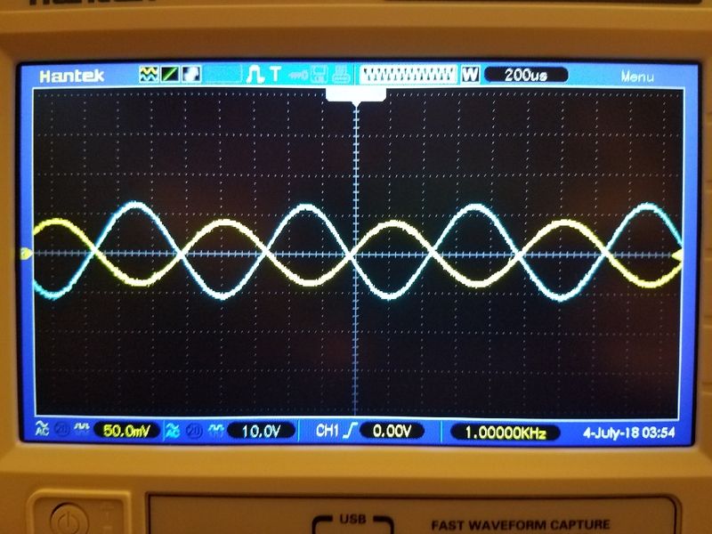
And now, for the grand finale....let's crank this bitch and see what the signal does. Volume on 10. Kapow.
Image

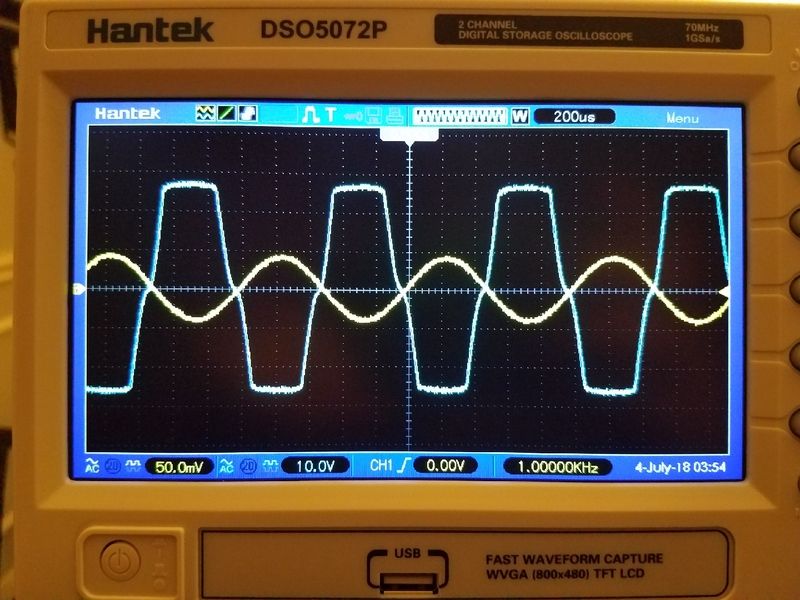
As you can see, we're full on clipping. That's a lot of signal, and it's been hammered by sweet ass natural power stage clipping. We start with 50 mv and pump out over 20 volts. That's an amplifier doing work....amplifying! We've turned that puny sine wave into a pretty substantial symmetrical square wave, and that's our wonderful all natural amp distortion.

For clarification...that output voltage is actually lowered from what's inside the amp at the power tubes. That shit is hundreds of ass shocking volts on the inside, but it's low amperage. We can't drive speakers with all that voltage and no amperage. So enter the output transformer. It does exactly what it's name implies - it transforms the high voltage low amp inside signal to speaker driving low voltage high amperage signal.

And that's that for now.
Rebel Yell
User avatar
jonny deep
Posts: 521
Joined: Thu Jan 05, 2017 9:25 am

Re: Let's build an amp! Greg's journey to electrocution

Post by jonny deep »

Awesome. So it was some interference that blue wire was picking up in the old position messing with your signal?
User avatar
Greg_L
Posts: 20668
Joined: Wed Jan 04, 2017 1:07 pm
Location: Where the knuckle meets the poophole

Re: Let's build an amp! Greg's journey to electrocution

Post by Greg_L »

jonny deep wrote: Wed Jul 04, 2018 7:50 am Awesome. So it was some interference that blue wire was picking up in the old position messing with your signal?
Sort of. I think that little loop of blue wire was causing the interference.

Here it is clipped out of the schematic:
rev tube.jpg
I drew on it in blue. That tiny little link connecting the plates of that tube carries over 400 volts DC. 410 VDC on the 1964 era schematic. On my amp with today's higher wall voltages it has about 425 VDC. That's damn near as much DC as anywhere else in the amp.

I looped it back around the tube the other way and all is good now.
You do not have the required permissions to view the files attached to this post.
Rebel Yell
User avatar
Bubba
Posts: 3350
Joined: Wed Jan 04, 2017 2:45 pm
Location: Checking out my haggard face in the mirror.

Re: Let's build an amp! Greg's journey to electrocution

Post by Bubba »

Is it right that the output signal is 180 deg out of phase with the input one?
Haggard Musician :mad:
User avatar
Greg_L
Posts: 20668
Joined: Wed Jan 04, 2017 1:07 pm
Location: Where the knuckle meets the poophole

Re: Let's build an amp! Greg's journey to electrocution

Post by Greg_L »

Bubba wrote: Thu Jul 05, 2018 5:03 am Is it right that the output signal is 180 deg out of phase with the input one?
I'm not 100% sure, but my rudimentary understanding tells me it doesn't matter. The guitar signal gets flipped a few times throughout the amp depending on how it goes into and out of a tube. A typical gain stage has the signal come into the tube on the grid, and it exits out of phase off the plate. And one half of it gets flipped again at the phase inverter. So I suppose it's possible that after an odd number of flips and flops that it can be 180 deg different at the output. Now that I'm thinking about it, I'm gonna investigate it further.

The number of gain stages matters too. On this amp, the two channels can't be jumpered and blended because the Vibrato channel has one more gain stage than the Normal channel. That one extra gain stages flips the signal out of phase. Where they'd combine later puts the whole thing out of phase and you get a really thin weird sound at the speaker.
Rebel Yell
User avatar
Bubba
Posts: 3350
Joined: Wed Jan 04, 2017 2:45 pm
Location: Checking out my haggard face in the mirror.

Re: Let's build an amp! Greg's journey to electrocution

Post by Bubba »

It might have an effect when generating blossoming feedback because you would want the string's resonance to be in phase with the speaker to get the best positive feedback. That said, the distance between your guitar and the speaker and the frequency of the played note would be critical too. I suppose that's why changing your position regarding the amp enables you to "tune in" on the feedback, like changing the position of an aerial.

In general, I don't think it matters, as you say. The fact that the signal peaks are perfectly coincident says to me that it's just the result of general flip-flopping of phase through the amp and it doesn't matter which way it ends up.
Haggard Musician :mad:
Post Reply