Let's build an amp! Greg's journey to electrocution

Re: Let's build an amp! Greg's journey to electrocution
Still watching... This is uber cool gerg..

Re: Let's build an amp! Greg's journey to electrocution
Thanks.
I don't think I'll get to it much today. I'm gonna go on one of my music store runs and finger bang all sorts of gear today. I'll be gone most of the day.
One thing I did do this morning though, and it's very important, is fucking clean up. Lol. Man I had shit everywhere. So much for being meticulous and clean. My immediate work area is organized, but the bits of wire and insulation and solder blobs and just general empty boxes and packaging and shit floating in the orbit of my work area was expanding and starting to catch the eye of the missus. Can't have that. Lol. So I cleaned up and reorganized. We're good to go again.
Rebel Yell
Re: Let's build an amp! Greg's journey to electrocution
Did a little amp work today. I'm starting to think about where the board is going to go, and how tall I'll need to make my standoffs. Where am I going to run my ground buss? Where the hell is the bias pot going to go? Before I can do any of that, I need to finish the power wiring, and do it in a way that is less risky for electrocution.
The "Fender way" could shock the hell out of me even with a blown fuse or some other failed component because the wall power goes to the switch first, which is just crazy dumb. So I modified the routing. I'm going....
Wall hot to fuse tip
Fuse tip to fuse shell
Fuse shell to power switch
Power switch to power transformer.
This way, the fuse sees juice first, and can protect everything else like a fucking fuse is supposed to.
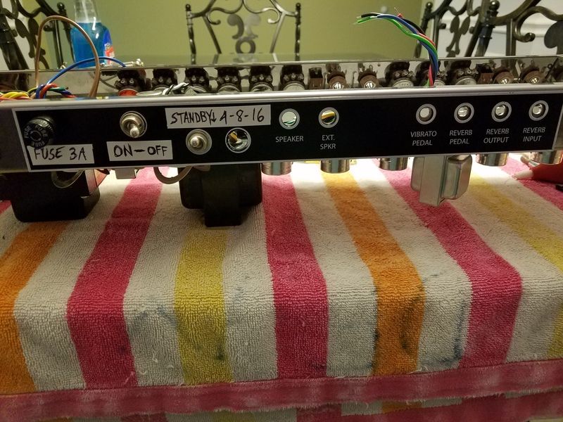
But even before we do that...let's move the fuse holder closer to the power supply....and everything else over with it. This is my new rear panel layout that I talked about earlier. Looks ghetto and totally DIY and I fucking love it.
Now we can finish wiring the power supply.
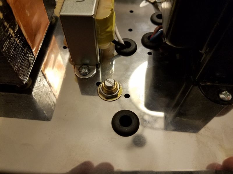
First I had to fix my little error and move the mains power ground. New hole drilled, no problem.
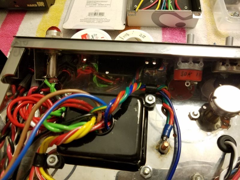
Fuse holder tip connected and sealed in shrink tubing. That tip is hot, and we don't ever wanna touch it. From there we go to that little sideways switch next to it, and the blue wire runs power back to the PT.
While we're down there, one of the "lower layers" of the wiring are the output transformer primary wires. They are the blue, brown, and red wires coming off the OT. We don't need the red wire yet, but the blue and brown wires go to pin 3 on each power tube. A very common error is to get these reversed, which yields a deafening squeal at startup....and looking at my OT schematic, I think I've done just that. I'm gonna research and verify it. The fix is simple - just reverse the wires. Swap blue and brown on each tube. I left enough slack in anticipation for this problem.
Moving on....the last major section of the power supply side of the amp is the "bias board" and pot. The pot mounts to the chassis and the bias board tucks way up in a virtually impossible to reach portion of the chassis. Problem - there is no hole to mount the bias pot. This chassis is full of holes, and none of them are for a the bias pot. No big deal. Time to drill again.
This looks like a good enough spot for a pot. Boom. It rhymes. The main board is just dropped in it's general location to see how the pot is gonna fit with everything else.
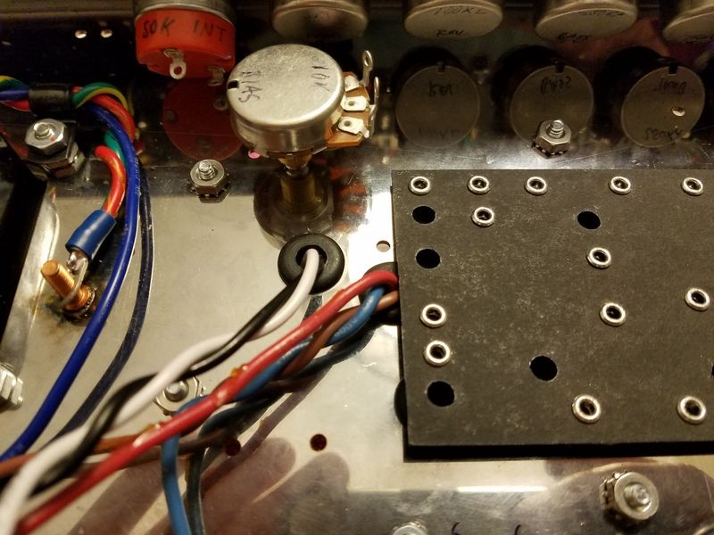
X marks the pot spot. Damn I'm killing it today.

Big ass hole.
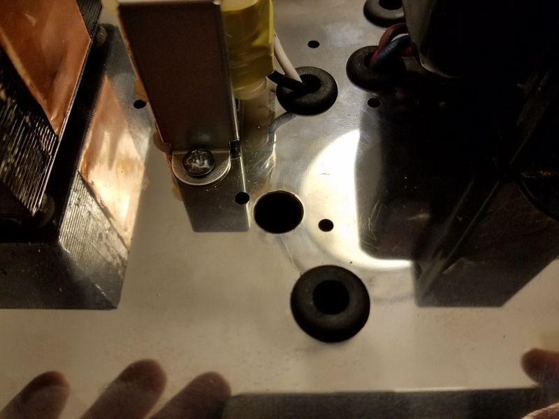
Fuck we gotta clean this up.
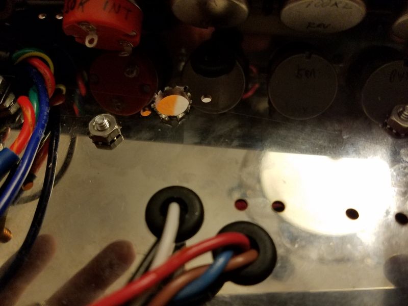
I may be a little biased but that bias pot is in the right spot!
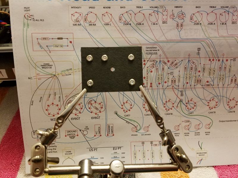
Okay enough with the shitty puns and rhymes. This is the creepy cranny the bias board has to go into - that little dark corner between the pilot light and tremolo pot. Thankfully there is actually a damn mounting hole in there.
And this little fucker is the bias board. This will be the first board that we'll start populating with caps and resistors. And the final PT wire that we need to use will attach to this board. This will supply the bias voltage that we will need to keep the power tubes alive.
So I guess next up will be that little bias board.
The "Fender way" could shock the hell out of me even with a blown fuse or some other failed component because the wall power goes to the switch first, which is just crazy dumb. So I modified the routing. I'm going....
Wall hot to fuse tip
Fuse tip to fuse shell
Fuse shell to power switch
Power switch to power transformer.
This way, the fuse sees juice first, and can protect everything else like a fucking fuse is supposed to.
But even before we do that...let's move the fuse holder closer to the power supply....and everything else over with it. This is my new rear panel layout that I talked about earlier. Looks ghetto and totally DIY and I fucking love it.

Now we can finish wiring the power supply.
First I had to fix my little error and move the mains power ground. New hole drilled, no problem.

Fuse holder tip connected and sealed in shrink tubing. That tip is hot, and we don't ever wanna touch it. From there we go to that little sideways switch next to it, and the blue wire runs power back to the PT.

While we're down there, one of the "lower layers" of the wiring are the output transformer primary wires. They are the blue, brown, and red wires coming off the OT. We don't need the red wire yet, but the blue and brown wires go to pin 3 on each power tube. A very common error is to get these reversed, which yields a deafening squeal at startup....and looking at my OT schematic, I think I've done just that. I'm gonna research and verify it. The fix is simple - just reverse the wires. Swap blue and brown on each tube. I left enough slack in anticipation for this problem.

Moving on....the last major section of the power supply side of the amp is the "bias board" and pot. The pot mounts to the chassis and the bias board tucks way up in a virtually impossible to reach portion of the chassis. Problem - there is no hole to mount the bias pot. This chassis is full of holes, and none of them are for a the bias pot. No big deal. Time to drill again.
This looks like a good enough spot for a pot. Boom. It rhymes. The main board is just dropped in it's general location to see how the pot is gonna fit with everything else.

X marks the pot spot. Damn I'm killing it today.

Big ass hole.

Fuck we gotta clean this up.

I may be a little biased but that bias pot is in the right spot!


Okay enough with the shitty puns and rhymes. This is the creepy cranny the bias board has to go into - that little dark corner between the pilot light and tremolo pot. Thankfully there is actually a damn mounting hole in there.

And this little fucker is the bias board. This will be the first board that we'll start populating with caps and resistors. And the final PT wire that we need to use will attach to this board. This will supply the bias voltage that we will need to keep the power tubes alive.

So I guess next up will be that little bias board.
Rebel Yell
Re: Let's build an amp! Greg's journey to electrocution
Are you gonna put the little bias jacks on the back of this thing that you plug your meter into??? If I overlooked this, pay no attention dude...
If you are, I was gonna suggest putting the bias pot on the back panel, but I guess it really doesn't matter because you'd have to pull the chassis out of the headshell to swap tubes anyway, right???
You do some pretty neat work Greg, so far this thing looks really good...
If you are, I was gonna suggest putting the bias pot on the back panel, but I guess it really doesn't matter because you'd have to pull the chassis out of the headshell to swap tubes anyway, right???
You do some pretty neat work Greg, so far this thing looks really good...

Gibson, Fender, Ibanez, Jackson
Ceriatone, Marshall, EVH
TC Electronic, MXR, Yamaha
My music @ Reverbnation
Re: Let's build an amp! Greg's journey to electrocution
I am planing to add bias test points to the rear of the chassis.Minerman wrote: ↑Sun May 06, 2018 7:24 pm Are you gonna put the little bias jacks on the back of this thing that you plug your meter into??? If I overlooked this, pay no attention dude...
If you are, I was gonna suggest putting the bias pot on the back panel, but I guess it really doesn't matter because you'd have to pull the chassis out of the headshell to swap tubes anyway, right???
You do some pretty neat work Greg, so far this thing looks really good...
The bias pot is gonna stay where it is though. I don't want that thing exposed, getting bumped, getting touched, etc. Also, putting it on the back would require long wire runs and I don't want that.
The head box is configured with a back panel that can be removed so I can swap tubes and adjust bias without removing the chassis. The bias pot sticks through the chassis and is adjusted externally.
Rebel Yell

Re: Let's build an amp! Greg's journey to electrocution
Beautiful work Greg.
I knew it would be.
I knew it would be.
-
WhiskeyJack

- Site Admin
- Posts: 11427
- Joined: Sun Jan 12, 2014 11:48 pm
- Location: Canada
- Contact:
Re: Let's build an amp! Greg's journey to electrocution
Dude. Thats sick.
So awesome. I honestly think that when this is done and dusted it really deserves a follow up video man. I know you do not do videos but i really think it will need a video. Even if just a walk through.
So awesome. I honestly think that when this is done and dusted it really deserves a follow up video man. I know you do not do videos but i really think it will need a video. Even if just a walk through.
Re: Let's build an amp! Greg's journey to electrocution
Thanks Boob. It's going well....so far.
Well, I don't know. I don't know how to do video beyond just filming with my phone, and that aint no good. If I ever do a video it'll have to be good quality, and that aint happening.WhiskeyJack wrote: ↑Mon May 07, 2018 1:04 pm Dude. Thats sick.
So awesome. I honestly think that when this is done and dusted it really deserves a follow up video man. I know you do not do videos but i really think it will need a video. Even if just a walk through.
Rebel Yell
-
Bubba

- Posts: 3350
- Joined: Wed Jan 04, 2017 2:45 pm
- Location: Checking out my haggard face in the mirror.
Re: Let's build an amp! Greg's journey to electrocution
Still enjoying this immensely.
Haggard Musician 

Re: Let's build an amp! Greg's journey to electrocution
Just put your phone on a tripod holder thing and film it. Then just upload it. It doesn’t gotta be fancy, the material is what’s important. And people love this nerdy shit!
Re: Let's build an amp! Greg's journey to electrocution
What would yall wanna see? A large portion of this so far has been me just sitting there measuring wires out and going back and forth to the schematic and test fitting things and boring shit like that. For every one solder joint there is like 30 minutes of prep. Lol. I'm having great fun but I can't imagine someone watching video of this.
But here's today's progress in pic form....
I feel like I've spent a lot of time today for not much stuff. But it's been important stuff.
We left off at that little bias board. Well here it is all wired up.

And here it is installed in it's little corner.

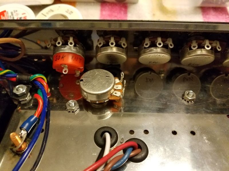
And here is the bias pot 2/3 wired up. The middle lug will have a wire that goes to the turret board.

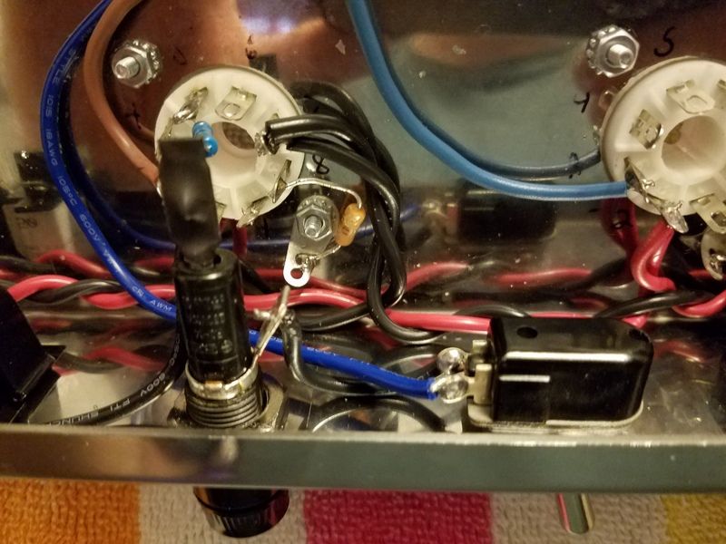
Here's where I had to get shade-tree mechanic on one of the pieces. That big ol impedance selector switch that I've been undecided on...well I decided. It was too big for the chassis, and I really wanna use it, so I fired up the air compressor and dug out the old pneumatic cutoff wheel. I had to lop off the bottom part of the switch so it would fit in the chassis...and bend the pins in.


And.....it fits!!!! And most importantly, it still works.

And finally the rear panel is almost complete.

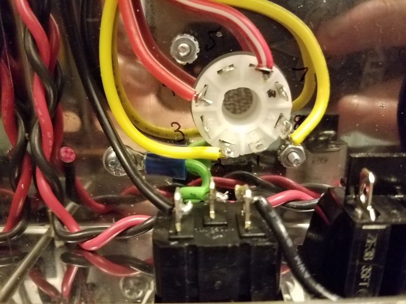
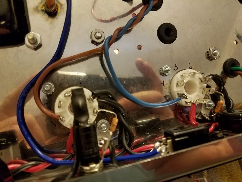
Now we gotta wire it to the output transformer secondaries and speaker jacks. This is "Marshall style"...so naturally I love it. The yellow (4 ohm), Green (8 ohm), and Brown (16 ohm) wires come from the tranny, go through the switch, and on to the speaker jacks through the blue wire. The hard to see black wire hidden in all that is the OT ground and it grounds at the speaker jacks. I'm not 100% on grounding it like that yet, but it will work. I'm just not sure about ground loop potential.

So the power supply is pretty much all done. This is that area of the chassis. I also added the 470 ohm screen resistors on the power tubes. Each tube's pin 6 is not soldered yet because there will be another wire added to that pin later.

Impedance selector switch area.

And the whole shebang as it sits right now. One week ago it was an empty chassis.

So, all that's left for the rear panel right now are the RCA jacks for the reverb/tremolo transformer and footswitch. Maybe tonight I'll work on that. Or maybe that's enough for today. But we are getting very near to populating the turret board. That will be nerve-racking.
Rebel Yell
Re: Let's build an amp! Greg's journey to electrocution
The black'n'red wires neatly twisted & reflected by the sides look like plaiting. Impressive work overall.
I have no real understanding of such hing s but, "...470 ohm screen resistors on the power tubes..., was that your decision? If Y, why?
I have no real understanding of such hing s but, "...470 ohm screen resistors on the power tubes..., was that your decision? If Y, why?
Cheers
rayc
rayc
Re: Let's build an amp! Greg's journey to electrocution
Thanks Ray.
No they're part of the schematic. The screen grid resistors help control oscillation and help keep the screen grid positively charged but keep current in check to aid the plate in sucking up electrons from the cathode. 6V6's don't draw massive screen current, but the grid control resistors need to be there. I'm using 1 watt, but I may bump them up to like 3-5 watts...because this amp will be abused.
Rebel Yell
Re: Let's build an amp! Greg's journey to electrocution
These....
You do not have the required permissions to view the files attached to this post.
Rebel Yell
Re: Let's build an amp! Greg's journey to electrocution
Thanks Greg.
"...this amp will be abused." is a positive statement.
"...this amp will be abused." is a positive statement.
Cheers
rayc
rayc
Re: Let's build an amp! Greg's journey to electrocution
Today might be mad scientist day. I'm gonna have to think about this one for a bit.....
I have this auxiliary mains outlet that is common to most vintage Fender amps. I had no plans to connect it. It would just be there to plug the hole. But....
What if I can re-purpose it for something useful? This idea popped into my head last night. I have little multimeter test jacks on order to make external bias testing points. The idea is to check and set bias without removing the chassis from the head shell. But to check and set bias, you need to know the plate voltage, and that requires removing the chassis, thereby totally defeating the purpose of the external test points. So I'd also need an external plate voltage test point. Plate voltage is dangerous though.
So my idea is to use that auxiliary outlet as a plate voltage or bias test point. It could be safe because you have to probe way in there to get a reading.
Option #1
Use the plug for the two bias test points and ground. Use one of the little sockets I've ordered for the plate voltage.
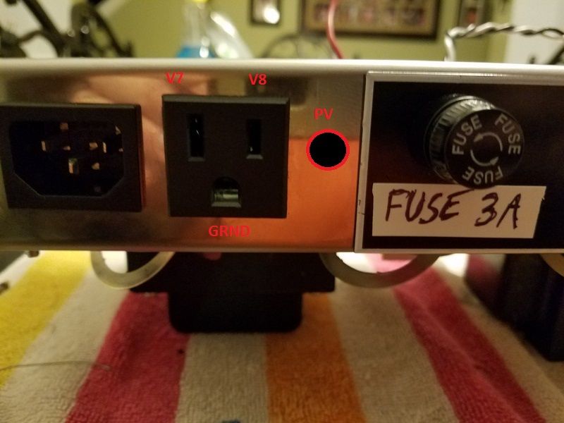
Option #2. This is probably safer. Use the wall plug for the plate voltage test point. Use two tip jacks for the bias points.
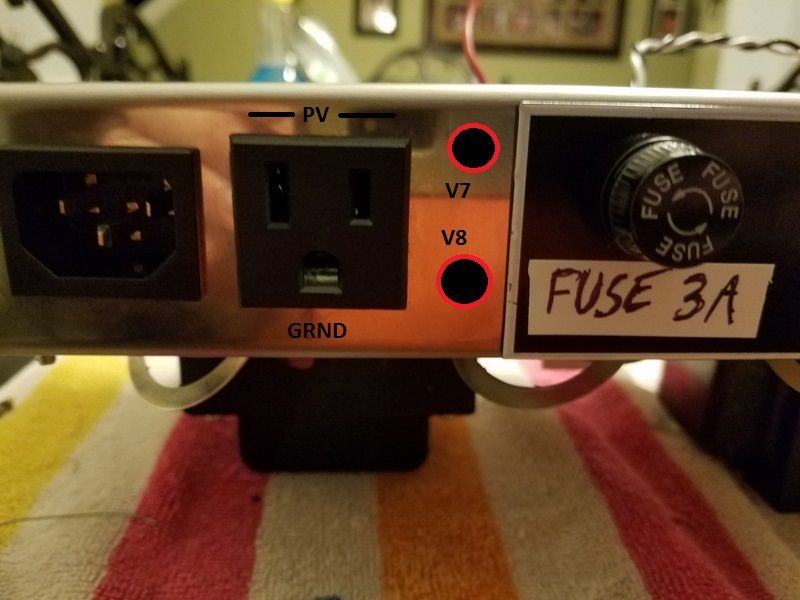
I think #2 would be better.
Rebel Yell
Re: Let's build an amp! Greg's journey to electrocution
pretty cool idea
Re: Let's build an amp! Greg's journey to electrocution
Thanks, now I'm thinking it's probably not all that necessary. I think I'll put a pin in that idea and maybe revisit it later. The bias test point is necessary, but I probably don't have to read plate voltage all the time.
Rebel Yell
Re: Let's build an amp! Greg's journey to electrocution
That is a cool idea Greg, it could be dangerous to someone who didn't know wtf it was for, but it'll be your amp, so that's probably not gonna be an issue...
Gibson, Fender, Ibanez, Jackson
Ceriatone, Marshall, EVH
TC Electronic, MXR, Yamaha
My music @ Reverbnation